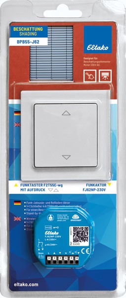
Impulse group switch for central control, 1+1 NO contacts not potential free 10A/250V AC, for 1 motor or motor relays. Standby loss 0.05–0.4 watt only. Modular device for DIN 60715 TH35 rail mounting. 1 module = 18mm wide, 58mm deep. This impulse group switch serves to implement commands generated by the sensor relays or by switches and push-buttons and controls a motor, a motor isolating relay MTR12-UC or a DC motor relay DCM12-UC dependent on the setting of the rotary switch on the front. 12 to 230V UC supply voltage and switching voltage at terminals +B1/-A2. The control voltage at terminals A3 up to A8 must have an identical potential. The function of this electronic group impulse switch is based on the principle that, on the one hand, impulse control is used to obtain UP-Stop-DOWN-Stop (contact 1 closed – both contacts open – contact 2 closed – both contacts open) and, on the other hand, additional control inputs can be used to select UP or DOWN as desired. Dynamic refers to control inputs for which one impulse of not less than 20 milliseconds is sufficient to close a contact. Static denotes a control input for which the contact is only closed as long as the control command is applied. UP and DOWN apply to roller shutters, Venetian blinds and roller blinds. For awnings, UP = retract and DOWN = extend. For windows UP = open and DOWN = close. Function rotary switches: AUTO 1 = When the lower rotary switch is in this position, the local advanced automatic reversing system for Venetian blinds is activated. When a pushbutton connected to A3+A4 (connected with a bridge) or A5/A6 connected to a dual push-button are used for local control a double impulse activates a slow rotation in the opposite direction, which can be stopped with a further impulse. AUTO 2 = When the lower rotary switch is in this position, the local advanced automatic reversing system for Venetian blinds is completely switched off. AUTO 3 = When the lower rotary switch is in this position, the local advanced automatic reversing system for Venetian blinds is switched off as well. The central control inputs A5 and A6 though, which are dynamic at AUTO 1 and AUTO 2, are static at first, thus, allow reversal of Venetian blinds by operating pushbuttons. They only switch to dynamic after 1 second continuous operation. Arrow up/arrow down = Arrow up (UP) and arrow down (DOWN) of the lower rotary switch are the positions for manual control. Manual control has priority over all other control commands. WA = Automatic reversal for Venetian blinds and awnings is controlled by means of the middle rotary switch. 0 = OFF, otherwise from 0.1 to 5 seconds ON with selected reversal time. In this case, it is only for DOWN that the direction is reversed on time-out of the time lag selected by means of the top rotary switch, e.g. to extend awnings or set Venetian blinds to a defined position. RV = The time delay (delay time RV) is set by means of the top rotary switch. If, the group impulse switch is in the UP or DOWN position the selected delay time runs (elapses). At time-out the device changes automatically to STOP. Therefore, the time delay must be chosen at least as long as the shading element or roller shutter will need to move from one limit position to the other. The LED indication for the delay times WA and RV is located behind this rotary switch. Local control with pushbutton connected to terminals A3+A4 (to be connected with a bridge). Each impulse causes the group impulse switch to change its position in the UP-Stop-DOWN-Stop sequence. Local control with roller shutter toggle switch connected to terminals A3 and A4. Local control with dual roller shutter pushbutton connected to A5 and A6. The UP or DOWN position is activated with an impulse by pushbutton. A further impulse from one of the two push-buttons stops the sequence immediately. Central control dynamic without priority connected to terminals A5 (UP) and A6 (DOWN). Up or DOWN is activated by a control signal. A further control signal (<700ms) at this control imput interrupts this process immediately, a further control signal (>700ms) continues the process. This is without priority because the local input A3+A4 (with bridge) and the central control inputs A7 and A8 can immediately override even whilst the control contact on A5 or A6 is still closed. Central control dynamic with priority connected to terminals A7 (UP) and A8 (DOWN). With priority because these control inputs cannot be overridden by other control inputs as long as the central control contact is closed. Otherwise it has the same function as the central control dynamic without priority. These central control inputs A7 and A8 are used for the sensor relays MSR12 and LRW12D for the wind sensor, the frost sensor and the rain sensor functions as these are required to have absolute priority over other sensor commands.
* Recommended retail price plus VAT.


